CNC Retrofit
An RB1 CNC retrofit with a Centroid ALLIN1DC.
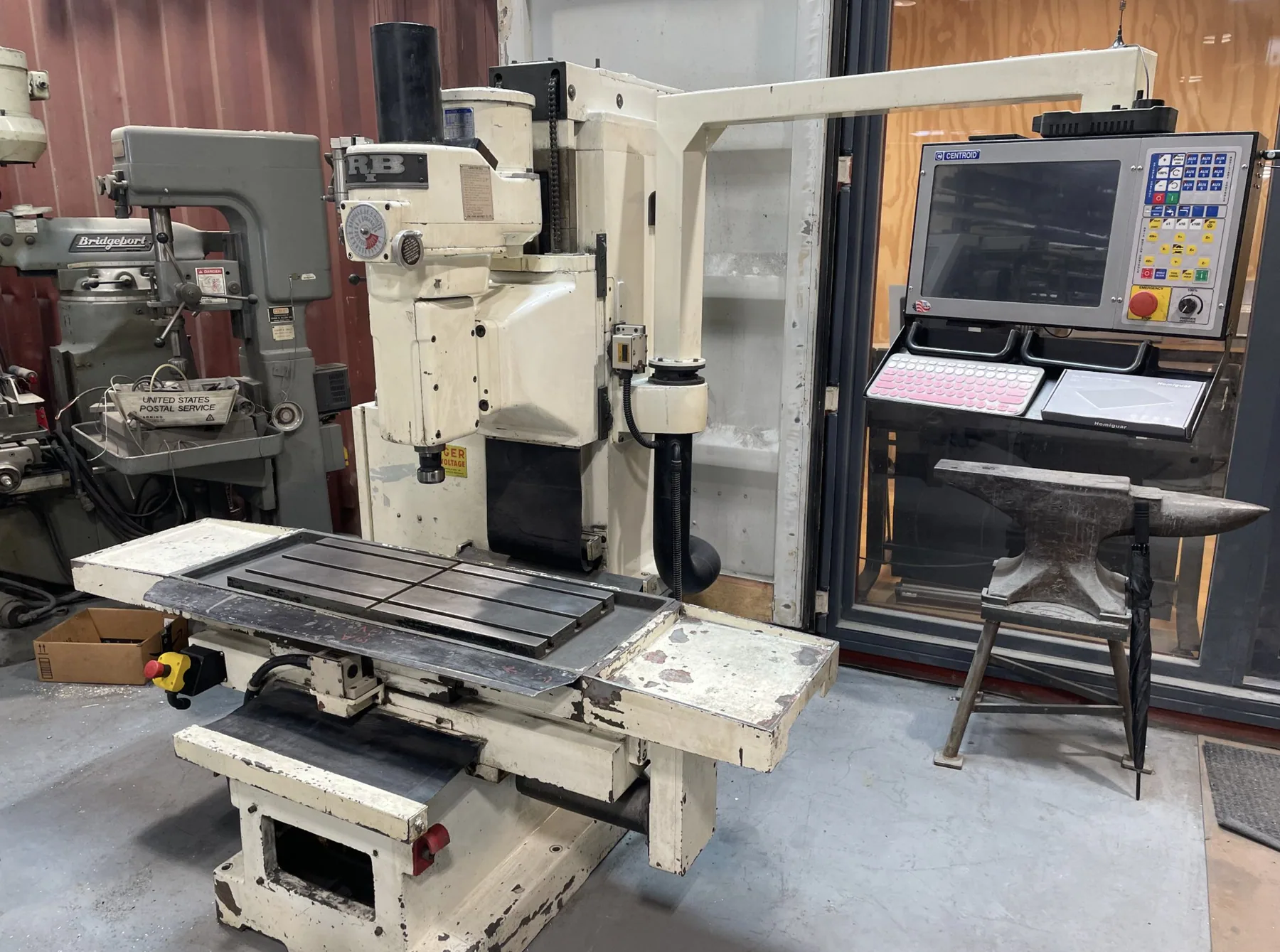
In the Summer of 2026, I was lucky enough to get a paid internship at Brooklyn based architectural fabrication firm RENZ+OEI. Over the course of the six weeks I was there, I worked on a couple of projects, mainly retrofitting and old CNC. The CNC had been in the shop for many years but had never run. The CNC was a Siber Hegner RB1 bed-type milling machine from the late 70s.
The owner of the shop had purchased around 50% of the needed components a couple years before, which simplified my job quite a bit. He had decided to run the machine with a Centroid ALLIN1DC controller. This made the wiring quite simple as the motor drivers were integrated into the main board. I began the process of the retrofit by giving the machine a good cleaning and tackling some of the smaller jobs that had to be done before diving into the main electronics.
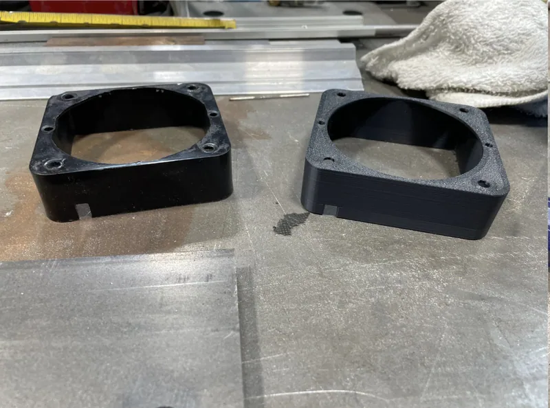
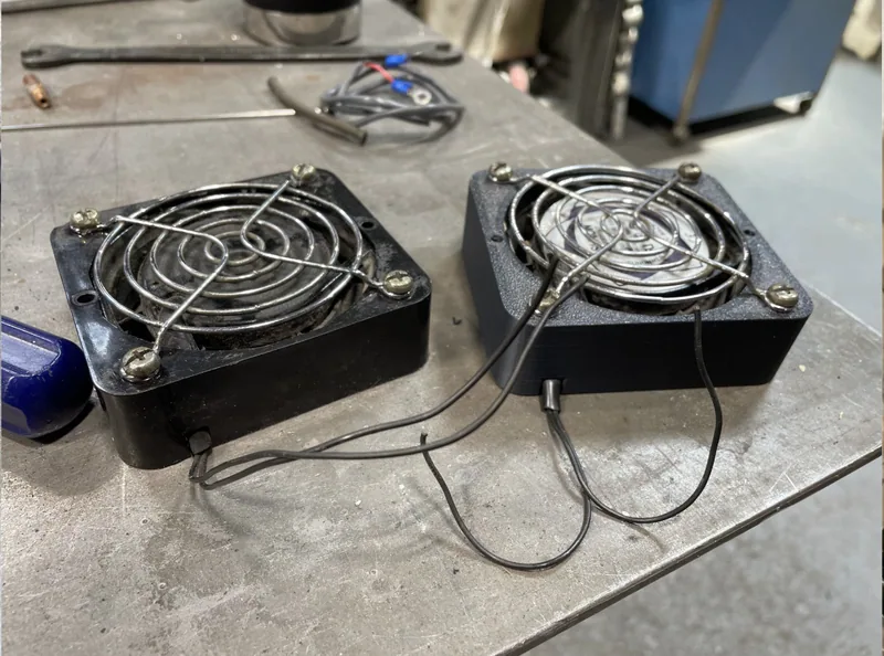
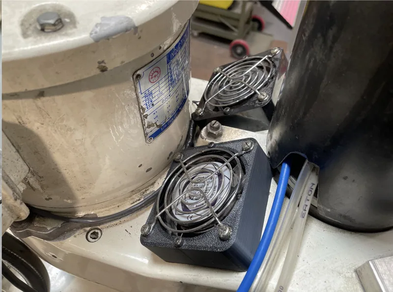
After cleaning the first thing I tackled was a missing fan bracket. The CNC had two 240v fans that cooled the spindle held in by injection molded brackets. Unfortunately there was only one bracket. I took the existing one and modeled up a duplicate in SOLIDWORKS and 3D printed it on the shop printer. It was a simple part but it worked as intended. I then installed the fans and tidied up the wiring on the spindle.
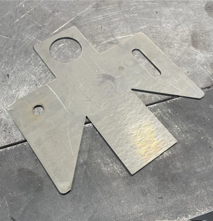
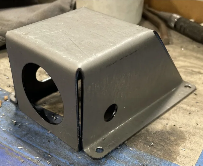
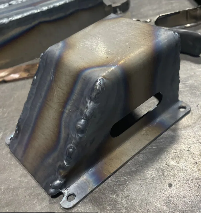
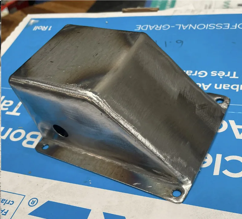
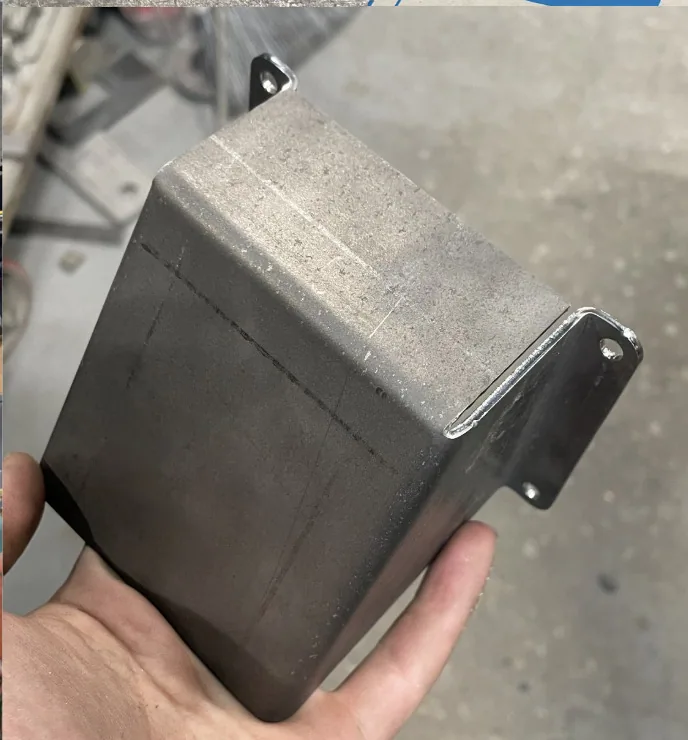
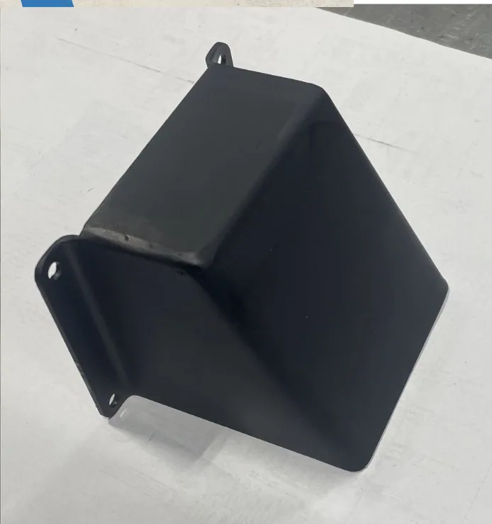
I then worked on two other brackets for the machine. First was an E-stop bracket (bottom right). I used the shop laser cutter to laser cut the flat pattern that I had designed in SOLIDWORKS out of 16 gauge steel. After cutting the parts, I used the massive hydraulic CNC press brake to form the bracket into shape. Then I TIG welded the seams together, ground them clean with an angle grinder, and then painted my bracket. I finished it up by mounting the E-stop button and drilling and tapping mounting holes into the machine's casting.
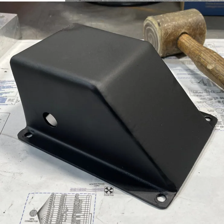
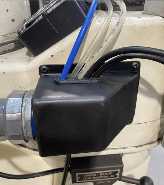
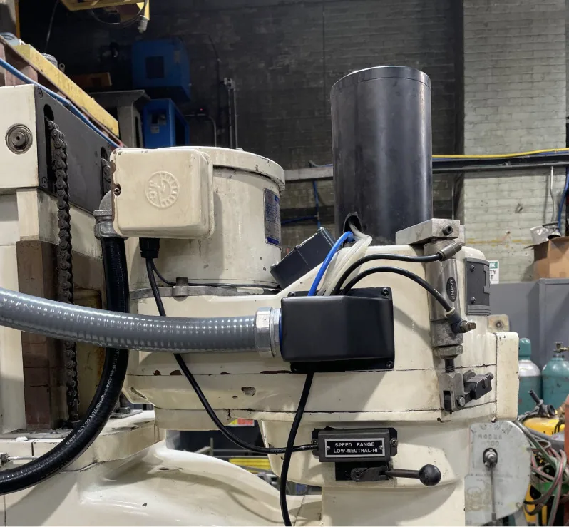
Next I worked on a bracket that would hold a large flexible conduit and have holes for incoming wires and air hoses. I again modeled it in SOLIDWORKS and cut it out on the laser. I bent, welded and painted it the same as the last one. For this bracket, as you can see in the sixth photo, I modeled and 3D printed a bushing that held the five air hoses at an angle and secured them to the bracket. I then drilled and mounted it to the machine head.
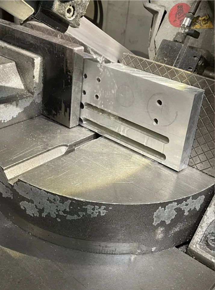
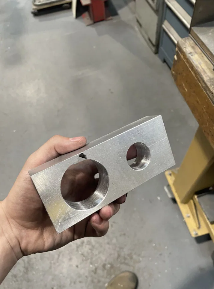
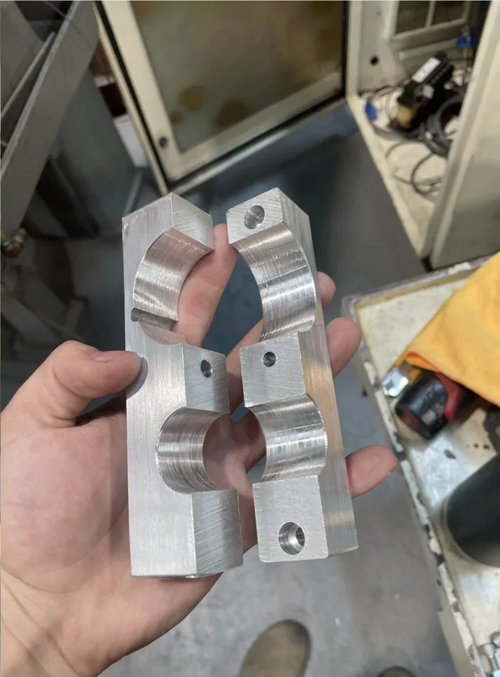
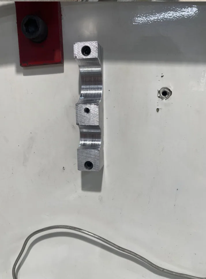
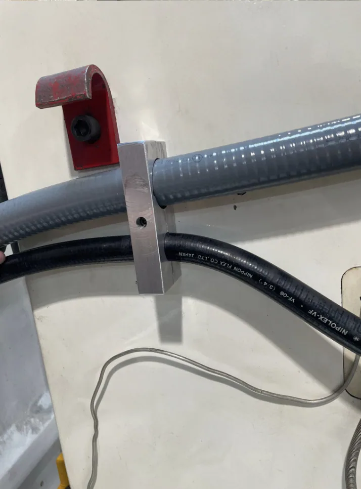
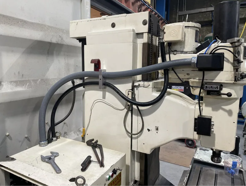
Following the construction of the bracket for the conduit. I made a guide bracket to hold the same conduit to the side of the machine. I started with a scrap chunk of aluminum that had some random holes in it. I sketched out my part onto the material to find the best orientation. After that I used the shop's horizontal bandsaw to chop the large piece into the size I needed.
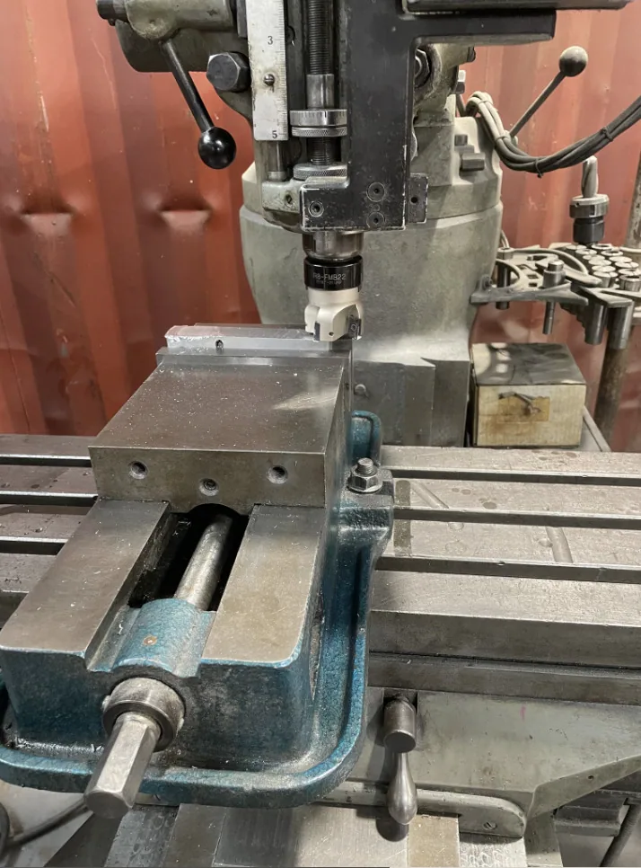
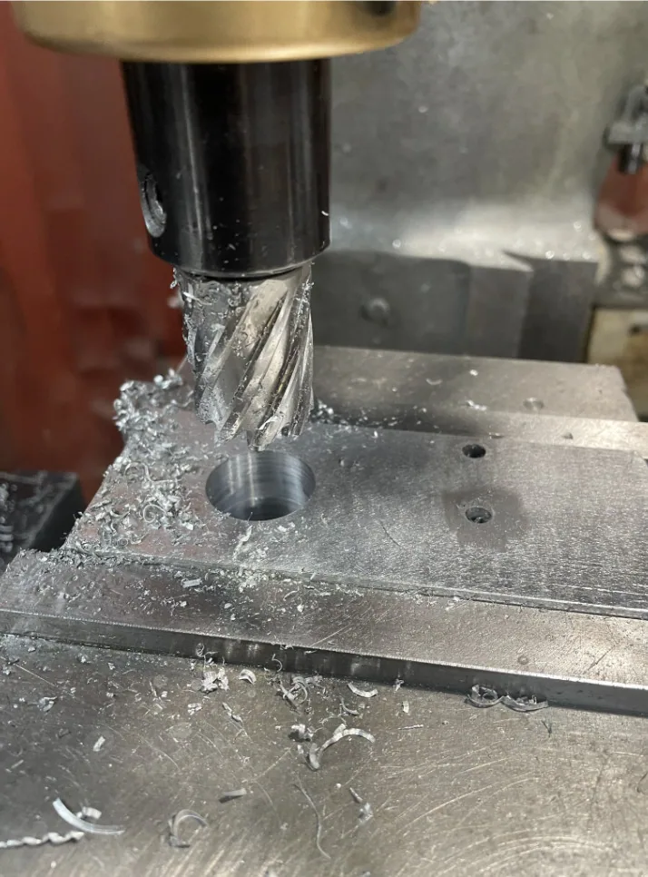
I left it slightly oversized, and faced it down to dimension on the shop's Bridgeport mill. I then mounted it horizontally and used two annular cutters to cut out the holes. I then brought it back to the band saw to chop it in half, and then back to the mill to make the counterbored mounting holes, plus a tapped hole for the top half to attach to the bottom. I cleaned it up on the belt sander and chamfered the edges using a wood router. I cut the conduit to size with an angle grinder and mounted it to the machine.
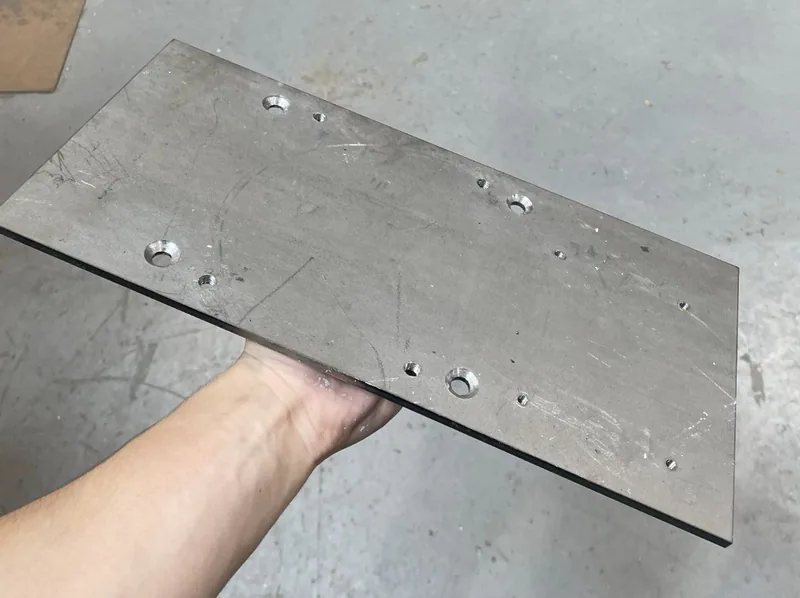
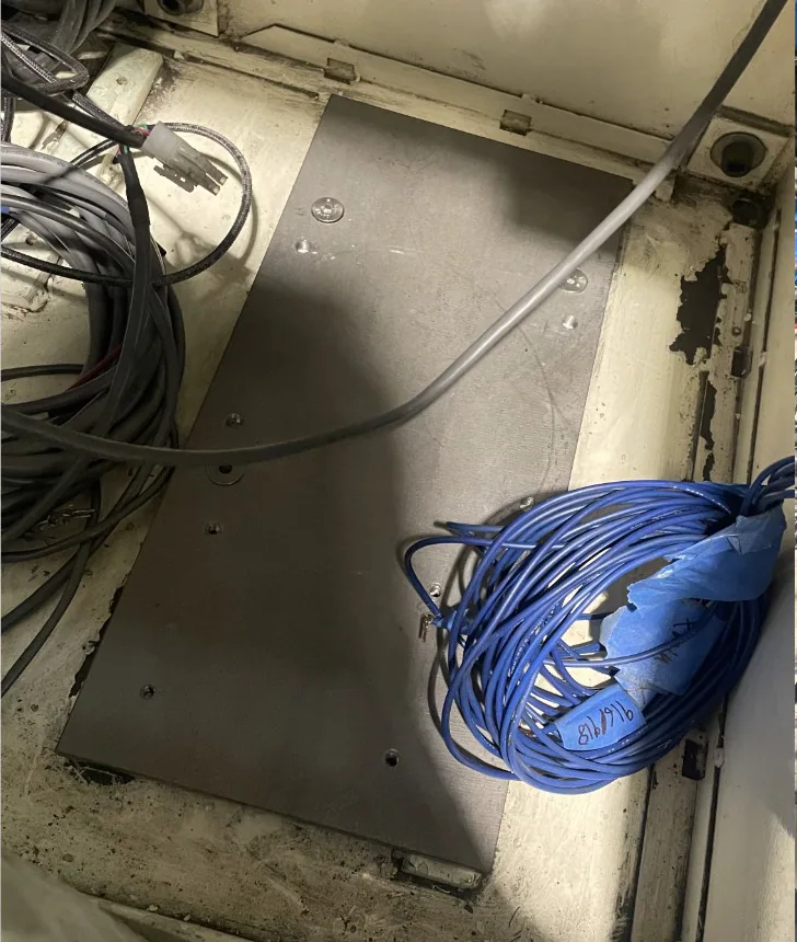
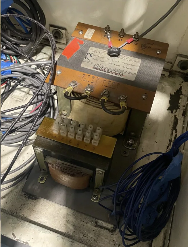
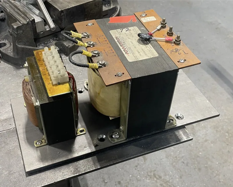
After making those brackets I decided to work more on the electrical side of things. I had been looking at the old transformers that were laying around and selected three to use. First a 110v one for the CNC PC, a 78v one for the servo motors (the motors used 100-150v DC, but after rectifying the 78v AC from the transformer I was left with ~110v DC), and a 24v one for controlling the contactors. The small 24v one was going to be mounted to the panel but the two larger ones, weighing around 30 pounds each, needed to be mounted to the floor.
In order to mount them to the floor of the cabinet I drew up a design for a panel that would give them places to mount. I laser cut this panel from a scrap of 1/4 steel from one of the other projects the shop was working on and drilled and tapped holes for the transformers. The panel mounted to the base of the cabinet with four countersunk bolts, and the transformers mounted to the panel with four more bolts each.
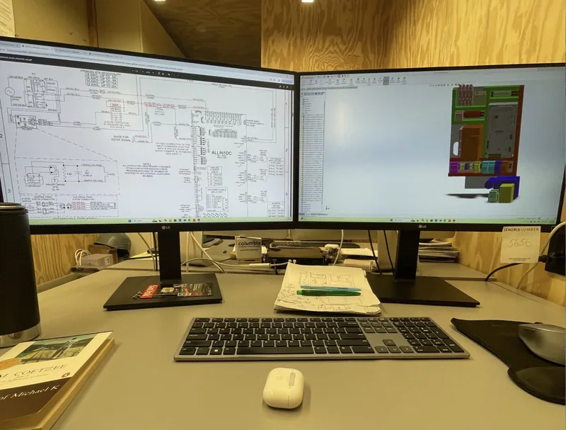
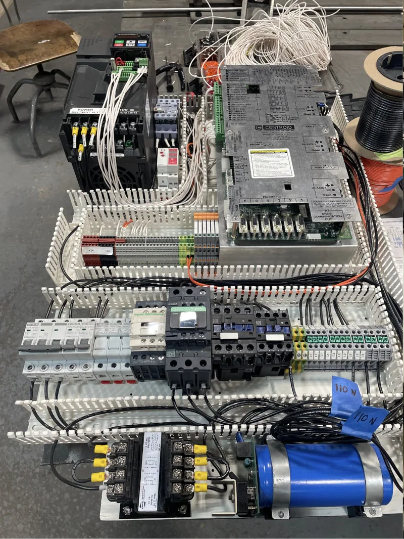
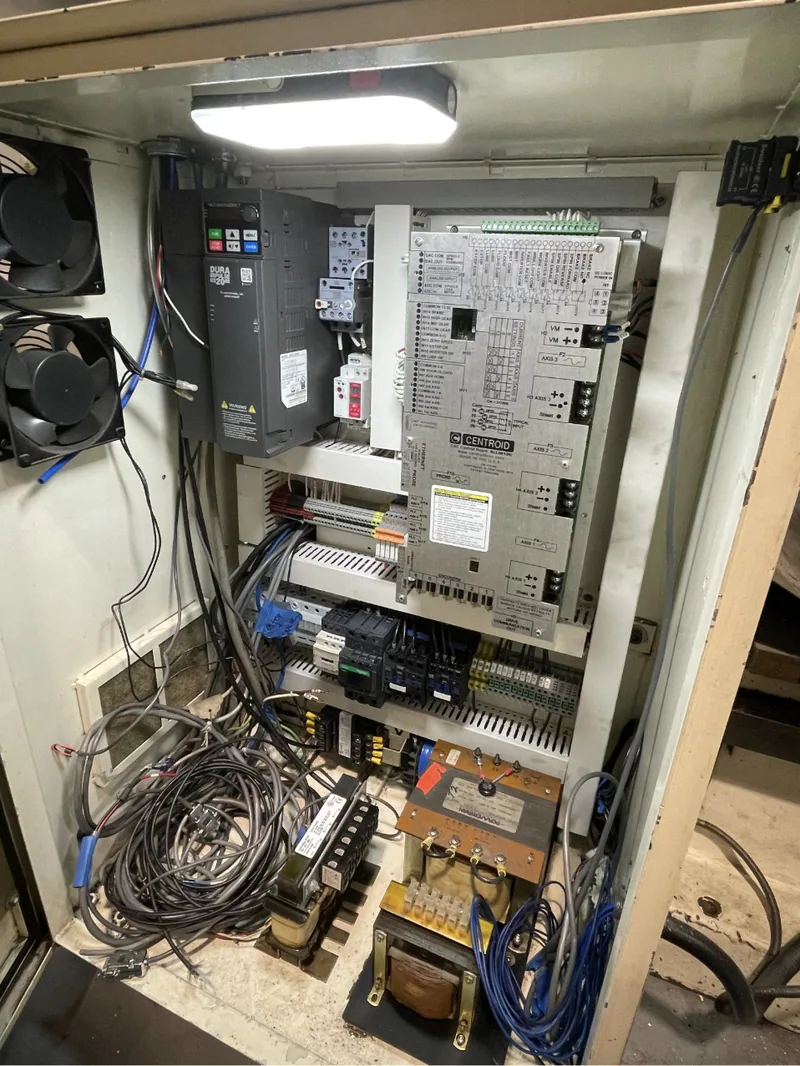
The brackets successfully completed, I began work on the main electrical control system. Based on the provided electrical schematics and discussions with my coworkers, I selected the components I would need for my retrofit. I was going to reuse an old VFD, the couple transformers I had found previously, and a couple contactors that were laying around the shop. I found 3D models online for everything and then imported them all into SOLIDWORKS to design a layout.
Next, components and layout decided, I began to drill and tap holes into the back panel to mount my large components. Once the VFD, main controller, and 24v transformer were mounted, I mounted my DIN rail and cable ducts. After that was the tedious process of wiring. I used a label maker to make heat shrink labels for every wire. After I completed as much of the wiring as I could out of the cabinet I installed the panel into the machine.
At this point I came to the end of my internship. I was pleased with the progress I had made, as was the owner of the shop.